 Calibration Strip Technology
Automated Calibration Stamp Technology for Improved In-Season Nitrogen Fertilization Agronomy Journal (in press)
_________________________________
CALIBRATION STRIP SPRAYER
David Zavodny
Biosystems and Agricultural Engineering Department
Construction
The OSU Calibration Strip Sprayer is designed for an all terrain vehicles (ATV) or utility type vehicles. The sprayer uses a 15 gallon ATV type elliptical tank equipped for mounting a 12 volt pump. The tank mounts on the rear rack of an ATV or in the bed of a utility vehicle and is equipped with a diaphragm pump capable of 4 gallons per minute at 30 psi. Two parallel booms with three sets of nozzles allows selection of three spraying rates. Boom height is adjustable. Nozzles are spaced 20 inches part with a 1/3 overlap. Other nozzles or spacings may be used, however the rates must be recalculated. Two solenoid valves with control switches and pressure gauge are used to select rates and turn the sprayer on or off.
An adjustable boom height feature is recommended for two reasons. First, nozzle height needs to be near 18 inches above ground level for proper spray coverage. Since most ATVs lower with an adult in the drivers seat, the boom height should be adjustable for different operators to keep the required 18 inch nozzle height for spraying. Also, the ATV will raise as the fertilizer level in the tank drops. Second, it is possible that the rear nozzles will contact the ground (or ramp, if backing on) while loading the ATV onto a pickup using ramps, if left at the spraying height. Again the boom can be quickly raised if this is a problem. An easy way to do this is with slip fit tubes, such as a 1-1/4 in. square tube that fits easily into a 1-1/2 in. square tube with a wall thickness of 3/32 (13 gauge) inch. A nut welded over a hole drilled through the larger tube allows a bolt to be threaded in to the nut to hold the smaller tube in place.
The booms consist of two 1.0 in. square tubes 44 in. long joined together with two ¼ x 2 in. steel straps 6 in. long welded to each tube. The tubes are spaced four inches apart.
See Figures 1 and 2. The nozzles attach to nozzle bodies that are clamped to each boom on 20 inch centers. The front boom tube bolts to two short bars, each welded to a 22-inch
long 1-1/4 in. square tube. The latter tubes then insert into two three-inch lengths of 1-1/2 inch square tube that are welded to the frame that bolts onto the rear rack of the ATV. The tank can be strapped to the frame or bolted down using brackets of the readers choosing.
Figure 1. Top view of double boom.
Figure 2. Rear view of boom and frame. Dimensions are examples and may not match those of readers.
The sprayer is equipped with a tee type strainer, a pressure gauge, a pressure relief valve, solenoid valves, and control switches. The tee strainer and relief valve thread onto opposite ends of the solenoid valve assembly. A port for the pressure gauge is built into some relief valves. Relief valves without this port require installation of a tee between the solenoid and relief valves. The valve assembly mounts on a bracket that bolts to the cross tube at the rear of sprayer frame. The pump mounts on top of the tank with four screws and draws fertilizer from the tank through a ½ or ¾ i.d. suction hose that is inserted into or connected to the bottom of the tank. The pump outlet connects to the tee strainer with ½ or ¾ hose. The relief valve bypass hose is ½ i.d. and returns to top of the tank. Hoses inserted directly into tank need a grommet in the tank port to prevent fertilizer spillage. Hoses from solenoid valves to nozzles are 3/8 i.d.
Figure 3. Plumbing diagram
The sprayer controller is supplied with a mounting bracket and attaches to the spray vehicle within easy reach of the operator. The controller should include at least three boom switches one of which can operate the pump -- a master switch, and a pressure gauge. Sprayer control systems that include the control, solenoid valves, and wiring harness are available from some of the suppliers listed below. Two boom switches select the solenoid valves that direct flow to the front or rear boom nozzles. The third boom switch controls the sprayer pump through a 15 amp or larger relay. The pressure gauge connects to a pressure port as previously mentioned with a 1/8 plastic hose that is supplied with the system harness. For longer gauge life, a chemical isolator can be plumbed into the gage line. Alternately a stainless steel gauge can be installed.
Note: Regulators that may be supplied as standard with these or similar systems are for high flow systems and are not used.
The electrical harness connects the control assembly to solenoid valves per manufacturers instructions. The left boom switch wires connect to the relay coil terminals rather than the left boom solenoid as listed in the instructions. The relay should have four tab or screw type connectors. The pumps positive wire (red) connects to one relay switch terminal. The other relay switch terminal connects to the vehicle battery positive post using a 10 or 12 gauge wire with 15 amp fuse. The pump ground wire connects to the battery ground post or a reliable frame ground. Use 10 or 12 gauge wire for this added wire length. If possible, all wire connectors should be soldered rather than crimped, then insulated with heat shrink tubing.
Figure 4. Electrical diagram
All materials, dimensions, and components are based on the units that OSU Biosystems and Agricultural Engineering Department built and can be modified as desired
Most sprayer components can be purchased through your local implement dealer or farm supply store. Specific trade names are used to assist the reader and do not imply endorsement by OSU. Some suppliers of the spraying components include:
Schaben Industries
239 S. Meridian
Newton, KS 67114
Phone 800-394-7662
Wylie Sprayers
5800 SW 11th
Oklahoma City, OK
888-665-5538
TeeJet Mid-Tech West (Spraying Systems Co.)
3500 S. Phillips Ave., Suite 125
Rapid City, SD 57105
605-338-5633
Texas Industrial Remcor
Box 3704
Temple, TX
254-982-4236
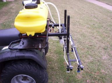
Sprayer on ATV
Controller on ATV
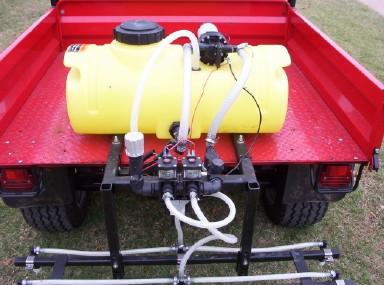
Sprayer on utility vehicle
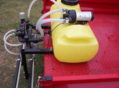
Side view of sprayer
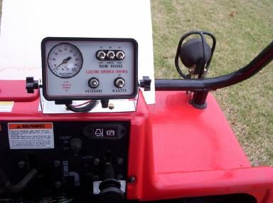
Controller on utility vehicle
Operation
This sprayer is designed to run at 5 miles per hour, therefore a speedometer is required on the vehicle. If your unit is not so equipped, portable Global Positioning System (GPS) units can be purchased that not only display travel speed, but also provide latitude and longitude information that can be used for recording locations. These units can be purchased at many sporting good stores and on the internet. They sell for about $150 and up, depending on the features.
Blue or pink marker dye is recommended for identifying areas that have been sprayed. It is available from several of the previously listed component suppliers in one quart bottles. The dye also assists in seeing the different fertilizer rates applied.
To set the relief valve initially, add a few gallons of water to the tank. Turn on both boom switches and the master switch, then turn on the pump control switch. The master switch must be turned on for either boom or the pump to function and should be turned off when not in use to prevent draining the battery. Once air has been purged from the lines, adjust relief pressure by turning the knob clockwise to increase pressure and counter clockwise to decrease pressure. This system should be set at 30 psi with both booms operating. Pressure will be slightly higher with only one boom spraying. Empty water from tank and fill with 28-0-0 liquid ammonium nitrate.
For each field, flag locations before spraying. Choose a representative area that is not susceptible to excessive drainage and other nuisances. Suggested strip sizes are 7-8 feet wide and 50 feet long with each of the three levels, placed next to one another. Do this at least twice in each field that you are putting strips on. The location can also be logged using a GPS receiver with WAAS.
Once the pump is running at set pressure, proceed to the marked field location and maintain speed at 5 mph. Switch on the desired boom for the length of the strip. Be sure to record the layout of rates at each site.
Note: At 5 mph the vehicle will travel about 7-1/2 feet per second.
Per acre nitrogen rates at 20 inch spacing, 30 psi and 5 mph using 28-0-0 liquid fertilizer for various nozzles are:
Nozzle Rate (Lbs N/acre)
TP8015-SS 20
TP8002-SS 27
TP8003-SS 40
TP8004-SS 53
TP8005-SS 67
TP8006-SS 80
Any two of these can be selected, with one size on each boom. Add rates together to get your maximum desired rate. Example: 80 lbs of actual N maximum per acre is desired. Equip one boom with TP-8002 nozzles (27 lbs N/acre) and the other with TP-8004 nozzles (53 lbs N/acre) to give 80 lbs N per acre.
Note: Rinse and flush spray unit thoroughly after use and especially before storing. Clean and touch-up any bare metal with spray paint before storing at end of season.
Suggested Bill of Materials
Notes: Quantities may vary depending on vehicle and preferences.
All bare steel parts should be painted before installation. Stainless steel bolts and nuts are recommended because of their resistance to corrosion that can be caused by fertilizers.
15 gallon ATV Spot Sprayer tank
12 volt diaphragm pump, 4 gpm at 30 psi
Sprayer Controller: Spraying Systems 90-50183 less regulator;
or
Texas Industrial Remcor RC1BL, less regulator;
or
Raven Electronics 063-0159-223 console & 115-0159-013 cable
Solenoid Valves: Spraying Systems AA144A-2
or
Texas Industrial Remcor 2100A-2 with 2149 bracket.
Pressure relief valve, ¾ NPT, adjustable.
Nipple, short, Polypro 3/4
Hose barb, ½ NPT-M x 3/8 Hose (2)
Hose barb, ½ NPT-M x ½ Hose (2)
Hose barb, ¾ NPT-M x ½ Hose (2)
Tee strainer, ¾ pipe thread, 30 mesh
Hose shank check valves, 3/8 hose, single (4)
Hose shank check valves, 3/8 triple (2)
Vari-spacing clamps (6)
Hose, 1/2 inch i.d., 50 psi minimum 5 ft.
Hose, 3/8 inch i.d., 50 psi minimum 20 ft
Hose clamps, 3/8-½ inch (16)
Fan nozzle, 80°, 0.3 gpm (3)
Fan nozzle, 80°, 0.6 gpm (3)
Nozzle caps with seals
(6)
Nozzle screens (6)
Hardware: Stainless Steel recommended
5/16 x ¾ in. bolts (4)
5/16 x 2-1/2 in. bolts (2)
3/8 x 1 in. bolts & nuts (2)
3/8 x 2 in. bolts & nuts (4)
3/8 x 2-1/2 in. bolts & nuts (4)
#10-24 x 1 screw (4)
Raw material:
1-1/2 in. sq. tube x 68 in.
1-1/4 in. sq. tube x 44 in.
1 in. sq. tube x 88 in.
¼ x 1-1/2 bar x 12
12 ga. Sheet, 14 x 24 (ATV tank channels)
3/16 x 1-1/2 angle (Utility tank mount)
Electrical:
Relay, 12vdc, 15 amp or larger
10 or 12 gauge insulated wire
Quick disconnect wire terminals, 10-12 gauge
Heat shrink tubing (optional)
Tools needed:
Screwdrivers, regular and Phillips Electric drill & bits
Welder Wire stripper/crimper
Combination wrenches ½ & 9/16 Soldering iron (optional)
Heat shrink gun (optional)
USEFUL FORMULAS
GPM = GPA x MPH X W
(Per Nozzle) 5,940
GPM = GAL/1000FT² x MPH X W
(Per Nozzle) 136
GPA = 5,940 x GPM (Per Nozzle)
MPH x W
GAL/1000FT² = 136 x GPM (Per Nozzle)
MPH x W
GPM -- Gallons Per Minute
GPA -- Gallons Per Acre
GAL/1000FT² -- Gallons Per 1000 Square Feet
MPH Miles Per Hour
W Nozzle spacing in inches
The formulas above are based on spraying water. Since liquid fertilizer weighs more than water, a conversion factor must be used. Once a nozzle size has been calculated using the formulas, multiply GPM or GPA by 1.13 for 28-0-0 fertilizer to determine the proper size nozzle.
Note: Liquid 28-0-0 fertilizer weighs 10.65 lbs./gallon and contains 3.0 lbs of actual nitrogen per gallon.
 Oklahoma
State University recently released the first automated calibration stamp
applicator for improving in-season fertilizer N rates and ultimate
Nitrogen Use Efficiency.
Oklahoma
State University recently released the first automated calibration stamp
applicator for improving in-season fertilizer N rates and ultimate
Nitrogen Use Efficiency.
